
Business
8 Mistakes US Businesses Make When Hiring a Vehicle Graphics Installer (And How to Avoid Them)

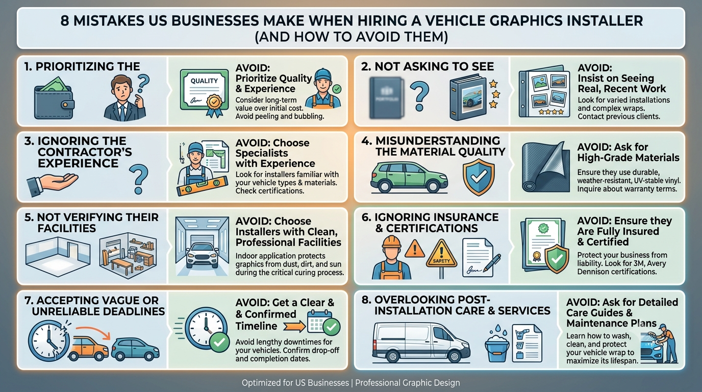
For businesses that operate fleets, service vehicles, or branded transport, the appearance of those vehicles is not a minor detail. It represents the company in every neighborhood, job site, and highway it passes through. When the graphics are poorly applied, misaligned, or peeling within months of installation, the cost goes well beyond the repair bill. It affects how customers perceive the business, how crews feel about their equipment, and how consistently the brand reads across multiple vehicles.
The decision to hire someone for this work is often treated as a one-time transaction rather than a vendor relationship that requires the same scrutiny as any other operational hire. That’s where most problems begin. Businesses across the US repeatedly encounter the same set of avoidable missteps when sourcing this type of work, and the consequences tend to compound over time.
What follows is a structured look at eight of those mistakes, grounded in how this work actually unfolds in real fleet and business environments.
Mistake 1: Treating Installation as a Commodity Purchase
A qualified vehicle graphics installer is not the same as a print vendor. Many businesses conflate the two and focus almost entirely on the cost of printing materials, overlooking the skill and process involved in the application itself. Installation quality determines how long graphics last, how cleanly they conform to vehicle contours, and whether they can be removed without damaging the original paint finish.
When the hiring decision is made based on price alone, businesses often end up with installers who lack the training or workspace conditions to do the work correctly. The result is graphics that lift at the edges, bubble under the surface, or fail to align properly across panels and doors.
Why Application Skill Determines Long-Term Value
Even premium materials perform poorly when applied incorrectly. Surface preparation, temperature control during application, and proper use of heat tools during conforming are all skills that separate experienced installers from those who learned on the job without formal training. A business that selects a provider based on the lowest quote is usually selecting based on the weakest process. What appears to save money at purchase frequently costs more to correct six months later.
Mistake 2: Skipping Verification of Portfolio and Vehicle Range
Not every installer has experience across the range of vehicles a business may operate. Applying graphics to a cargo van is a different task than wrapping a box truck, a flatbed trailer, or a vehicle with complex curves and recessed handles. Businesses often assume that experience with one vehicle type transfers automatically to others, which is not always the case.
Matching Installer Experience to Your Actual Fleet
Before committing to an installer, it’s worth asking to see documented examples of work completed on vehicles similar to yours. A portfolio that only shows passenger vehicles or simple panel installations may not reflect the capability needed for commercial fleet work. Gaps in a portfolio often indicate gaps in practical experience, and those gaps become apparent on the vehicle itself once the job is done.
Mistake 3: Ignoring Workspace and Environmental Standards
The environment in which graphics are applied has a direct effect on the outcome. Dust, humidity, cold temperatures, and direct sunlight all interfere with proper adhesion. Professional installers work in climate-controlled, enclosed environments specifically to control these variables. Businesses that allow or accept outdoor installation or work in unconditioned garages are accepting a higher risk of failure from the start.
What a Proper Installation Environment Looks Like
A professional installation space is clean, temperature-regulated, and free from environmental contaminants that can trap under the film during application. When an installer does not have a dedicated facility, or when the work is proposed to be done on-site in an open yard or parking area, those are signals worth taking seriously. The materials used in vehicle graphics are sensitive to temperature and surface condition, and no amount of skill fully compensates for a poor working environment.
Mistake 4: Failing to Clarify Warranty and Durability Expectations
Businesses often proceed without a clear understanding of what the installer stands behind after the job is complete. Warranty terms for vehicle graphics vary considerably between providers and are frequently not discussed during the quoting process. When issues appear within the expected lifespan of the material, having no documented warranty puts the business in a difficult position.
Understanding What Warranties Actually Cover
A manufacturer’s material warranty is not the same as an installation warranty. The material may perform as expected, but if the installation itself was flawed, that warranty offers no recourse. Businesses should ask directly what the installer covers in terms of adhesion failure, edge lifting, or color inconsistency that results from application error. Getting this in writing before work begins is a reasonable expectation for any professional service relationship.
Mistake 5: Underestimating the Importance of Brand Consistency Across a Fleet
For businesses operating more than one vehicle, consistency across the fleet matters more than perfection on a single unit. Color calibration, placement of logos, spacing, and finish should read identically from one vehicle to the next. When this is handled by multiple installers, or by a single installer without a documented template process, drift in appearance accumulates over time.
How Inconsistency Compounds Over Time
When vehicles from the same company look slightly different from one another, it creates an impression of disorganization. Customers and prospects who see those vehicles in different settings may not consciously register the inconsistency, but the professional impression is weakened. As established by branding research reviewed by the American Marketing Association, visual consistency across touchpoints reinforces recognition and trust, and vehicles are among the most visible of those touchpoints for service businesses.
Mistake 6: Not Accounting for Vehicle Age and Paint Condition
The surface condition of a vehicle affects how well graphics adhere and how cleanly they can eventually be removed. Older vehicles with oxidized paint, previous body repairs, or residual adhesive from prior graphics present challenges that a qualified installer should assess before beginning work. Businesses often present vehicles without disclosing their history, and installers who do not inspect thoroughly may apply materials to surfaces that will compromise the result.
Pre-Installation Assessment as a Standard Step
A thorough installer will examine the surface, identify problem areas, and communicate what surface preparation is needed before proceeding. Skipping this step, or working with an installer who does not raise these questions, increases the likelihood of early failure. Businesses should expect a brief assessment period before any installation begins, and should treat an installer who moves directly to application without inspection as a risk factor.
Mistake 7: Overlooking Removal Planning at the Time of Installation
Vehicle graphics are not permanent, and most businesses will eventually need to remove or replace them. The ease and safety of removal depend significantly on the quality of the materials used and how they were applied. Businesses that do not ask about removal at the time of installation often face difficult situations when fleet vehicles are repurposed, sold, or updated with a new brand design.
Why Removal Method Affects Your Total Cost
Poor-quality films or overly aggressive adhesives can damage paint during removal, resulting in repair costs that can exceed the original installation cost. Businesses should ask specifically about the material’s removal characteristics and whether the installer has experience with clean removal on vehicles of the age and finish type they operate. Planning for this at the beginning of the relationship prevents a costly situation at the end of one.
Mistake 8: Selecting a Provider Without a Clear Production and Scheduling Process
Fleet operations run on schedules, and vehicle downtime for graphics installation needs to be predictable. Businesses frequently choose installers without asking about turnaround time, scheduling flexibility, or how the provider handles multi-vehicle projects. When the process is undefined on the installer’s side, delays are common and difficult to resolve once the relationship is underway.
Scheduling and Process Clarity as a Business Requirement
A professional installer should be able to give a clear timeline from intake to completion, explain how vehicles are sequenced if multiple units are involved, and communicate proactively if anything changes. Businesses that operate fleets with tight dispatch schedules cannot afford ambiguity about when a vehicle will be available. Asking these questions before signing any agreement is not excessive — it reflects the legitimate operational constraints that the business is managing.
Conclusion: What a More Careful Hiring Process Looks Like
The mistakes outlined above are not unusual. They appear across industries and business sizes because the hiring process for this type of work is often treated informally, as though installation quality were a given once materials are selected. In practice, the opposite is true. The quality of the installation determines whether the materials perform as expected, whether the brand reads consistently, and whether the investment holds up over the intended lifespan of the graphics.
Businesses that slow down the vendor selection process, ask specific questions about workspace conditions, installer experience, warranty coverage, and production scheduling, tend to have significantly fewer problems after the work is done. They also build relationships with providers who understand their fleet, their brand standards, and their operational constraints.
Vehicle graphics are a functional investment in brand presence. The vehicles carrying those graphics move through real communities, work sites, and customer environments every day. The standard applied to the hiring decision should reflect that reality. A more deliberate process at the front end prevents avoidable costs, operational disruption, and brand inconsistency over the long term. That return on diligence is available to any business willing to apply it.



Efficient material movement is an important part of many business operations, particularly in warehouses, distribution centers, manufacturing facilities, construction environments, and other workplaces where products or supplies must be transported, positioned, stored, and retrieved regularly. When materials are moved manually or with equipment that does not match the requirements of the task, productivity can be affected and unnecessary strain can be placed on workers, equipment, and operational schedules. A well-planned approach to material movement considers the type and weight of loads, the distance materials need to travel, available storage space, operating surfaces, workflow patterns, and the frequency of handling activities. Businesses that evaluate these factors before selecting equipment can create a more organized process that supports daily productivity while making better use of available resources. The goal is not simply to have more machines available, but to ensure that the equipment used throughout the operation is appropriate for the work being performed.
Understanding the Role of Equipment in Material Movement
Material-handling operations often involve several different activities that may appear simple individually but become more demanding when performed repeatedly throughout the day. Loads may need to be lifted from the floor, transferred between locations, positioned on storage racks, moved across a facility, or loaded and unloaded from vehicles. Each activity can involve different equipment requirements, and a machine that works effectively for one task may not be suitable for another. Businesses should therefore look at their complete material flow rather than selecting equipment based on a single task. Factors such as load capacity, lifting height, maneuverability, turning radius, attachment requirements, operating environment, and frequency of use can all influence equipment selection. Understanding these requirements provides a stronger foundation for developing an efficient handling process and can reduce the likelihood of choosing equipment that is either insufficient for the work or unnecessarily large for the operating environment.
Matching Equipment Capacity to Actual Loads
Load characteristics are among the most important considerations when planning material-handling operations. Equipment should be capable of safely handling the typical loads encountered during normal work, while the maximum anticipated load should also be considered when evaluating capacity requirements. Weight alone is not always enough to determine whether equipment is suitable because load dimensions, shape, balance, and positioning can also affect how a machine performs. A long or unusually shaped load may require a different configuration or attachment than a compact pallet, even when the two loads have similar weights. Operators and fleet managers should understand the equipment’s rated capacity and operating limitations before using it for a particular application. Choosing equipment according to actual load characteristics helps support predictable handling and reduces the risk of using machinery beyond its intended operating parameters.
Considering Facility Layout and Maneuverability
The physical layout of a facility can have a significant influence on equipment selection and overall productivity. Narrow aisles, crowded storage areas, low-clearance doors, tight corners, loading docks, ramps, and uneven surfaces can all affect how easily equipment moves through the workplace. A machine may have sufficient lifting capacity but still be impractical if it cannot maneuver effectively within the available space. Businesses should consider aisle dimensions, turning areas, travel distances, floor conditions, and frequently congested zones when reviewing their equipment requirements. Thoughtful planning can help reduce unnecessary travel and improve the movement of materials between receiving, storage, production, and shipping areas. When equipment is appropriately matched to the physical environment, operators can spend less time navigating obstacles and more time completing productive handling tasks.
Supporting Warehouse Organization
Warehouse organization depends heavily on reliable material movement. Products that are received, stored, picked, transferred, and shipped must move through the facility in a predictable sequence. Equipment can support this process by helping employees position loads efficiently and maintain organized storage areas. However, equipment alone cannot solve poor workflow design. Businesses should also review how frequently certain products move, where frequently accessed materials are stored, and whether unnecessary transportation occurs between work areas. When equipment selection is coordinated with warehouse layout and inventory practices, businesses can establish more efficient movement patterns. This may also help reduce congestion and make it easier for employees to locate and handle materials without unnecessary delays.
Improving Workflow Through Equipment Planning
Effective equipment planning begins with an understanding of how materials actually move throughout an operation. Managers can observe receiving areas, storage zones, production spaces, and shipping locations to identify where delays or unnecessary movement occur. These observations can reveal whether equipment is being used efficiently or whether certain tasks require additional capacity. For example, repeated movement between distant areas may indicate a need to reorganize the workflow, while frequent equipment shortages during specific periods may suggest that temporary capacity could be useful. Planning around real operational patterns allows businesses to make decisions based on measurable requirements instead of assumptions. This approach can also help managers identify opportunities to improve productivity without making unnecessary changes to the entire operation.
Choosing the Right Type of Equipment
Different material-handling tasks require different equipment characteristics, and businesses should consider the specific purpose of each machine before making a selection. Some applications require lifting and stacking capabilities, while others depend more heavily on transportation, positioning, or access. Equipment may also need to work indoors, outdoors, or across multiple environments. Electric equipment may be appropriate for certain indoor applications, while other environments may require different power or performance characteristics. Attachments can further expand the functionality of equipment for specialized loads. The right selection process considers how frequently the machine will be used, what tasks it will perform, where it will operate, and what limitations exist within the facility. This makes it easier to create an equipment strategy that supports actual operational needs.
Preventive Maintenance and Equipment Reliability
Maintenance plays an important role in keeping material-handling equipment available for daily operations. Machines that operate regularly are exposed to wear involving tires, brakes, hydraulic systems, steering components, electrical systems, lifting mechanisms, controls, and other parts. Routine inspections and scheduled maintenance can help identify developing issues before they interfere with operations. Maintenance schedules should be based on manufacturer recommendations, operating conditions, equipment age, usage levels, and the type of work performed. Keeping accurate service records can also help managers understand recurring issues and plan future repairs or component replacement. A proactive maintenance approach can improve equipment reliability and help businesses make better decisions about when a machine should remain in service, receive major repairs, or be replaced.
Operator Awareness and Safe Equipment Use
Equipment performance also depends on how machines are operated. Employees who understand equipment controls, rated capacities, operating limitations, inspection procedures, and workplace rules are better positioned to use machinery appropriately. Training should reflect the specific equipment being used and the environment in which employees operate it. Operators should understand the importance of inspecting equipment before use and reporting unusual sounds, leaks, damaged components, warning indicators, or changes in performance. They should also be familiar with appropriate load positioning and travel practices. Consistent operator awareness supports both productivity and equipment preservation because machinery is less likely to be subjected to unnecessary misuse when employees understand its capabilities and limitations.
Managing Temporary Changes in Demand
Businesses do not always have consistent material-handling requirements throughout the year. Seasonal activity, large orders, facility renovations, inventory changes, special projects, and temporary equipment downtime can create periods when normal fleet capacity is insufficient. In these situations, temporary equipment can provide additional flexibility without requiring a permanent expansion of the fleet. A business may maintain a core group of machines for routine operations while obtaining additional capacity when demand increases. This approach can be useful when additional equipment is needed for a defined period rather than continuously. Managers can evaluate the expected workload, project duration, equipment specifications, and operating conditions before deciding whether temporary capacity is appropriate.
Evaluating Total Equipment Costs
Equipment decisions should consider more than the initial purchase price. Businesses may also need to account for maintenance, repairs, fuel or charging requirements, operator training, storage, insurance, downtime, replacement components, and eventual disposal or resale. An inexpensive machine may become less economical if it requires frequent repairs or does not perform efficiently for the intended application. Conversely, investing in equipment with appropriate capabilities may support more predictable operations over a longer period. Businesses should therefore evaluate the total cost associated with owning and operating equipment rather than focusing exclusively on acquisition price. This broader perspective can help managers compare different approaches and identify opportunities to use resources more effectively.
Integrating Equipment With Fleet Management
Businesses with multiple machines can benefit from maintaining accurate fleet information. Records can include equipment age, operating hours, service history, repair costs, utilization levels, and upcoming maintenance requirements. This information allows managers to identify which machines are heavily utilized and which may have lower levels of activity. It can also help reveal whether equipment shortages are caused by insufficient fleet capacity or inefficient allocation. A fleet management strategy can coordinate maintenance schedules, equipment availability, replacement planning, and future capacity requirements. Over time, these records provide useful information for making decisions based on actual operating history rather than relying entirely on assumptions or short-term observations.
Supporting Changing Business Requirements
Business requirements can change as operations grow, product lines expand, facilities are reorganized, or customer demand fluctuates. A handling strategy that works effectively for a smaller operation may not remain suitable after significant changes in workload or facility design. Managers should periodically review equipment utilization and material flow to determine whether the existing fleet continues to match current requirements. Businesses can also evaluate whether certain machines are underused while other equipment experiences excessive demand. This type of review can identify opportunities to rebalance fleet usage, modify workflows, or introduce different equipment capabilities. Regular evaluation makes it easier to respond to operational changes while maintaining an organized approach to material movement.
Using Material Handling Equipment More Strategically
Material handling equipment can support a broad range of operational activities when selected and managed according to actual workplace requirements. Businesses should consider equipment capabilities alongside workflow design, facility conditions, load characteristics, maintenance needs, and operator requirements. Rather than treating equipment as an isolated investment, managers can view it as part of a larger operational system in which storage, transportation, lifting, loading, and unloading activities are connected. This broader perspective can help identify inefficiencies and improve coordination between different stages of material movement. Strategic equipment planning also makes it easier to determine whether additional machines, replacement equipment, attachments, or temporary capacity may be appropriate as business needs evolve.
Planning for Long-Term Equipment Performance
Long-term performance depends on consistent attention to equipment condition, usage patterns, maintenance requirements, and changing operational demands. Businesses can establish useful equipment plans by maintaining service records, scheduling inspections, monitoring utilization, and reviewing recurring repair needs. Replacement planning should also begin before equipment reaches a point where unexpected failure becomes a major operational problem. When managers understand the expected workload and the condition of their existing fleet, they can plan capital expenditures more effectively and avoid making rushed decisions. Long-term planning can also include evaluating newer equipment technologies, changes in facility layout, and opportunities to improve energy efficiency or operator productivity. A structured approach gives businesses greater visibility into future equipment requirements.
Creating a More Organized Handling Strategy
An effective material-handling strategy combines appropriate equipment with thoughtful workflow planning, trained operators, reliable maintenance, and regular performance reviews. Businesses can begin by identifying the materials they move most frequently, understanding the characteristics of those loads, and mapping how they travel through the facility. From there, managers can evaluate equipment capabilities and determine whether existing machines are being used efficiently. Maintenance records and utilization information can provide additional insight into fleet performance, while operator feedback can reveal practical challenges that may not be visible from management-level reports. Bringing these sources of information together creates a more complete picture of daily material movement and provides a foundation for continuous improvement.
Conclusion
Reliable material movement requires more than simply having machines available when work needs to be completed. Businesses must consider load characteristics, facility layout, workflow, equipment capacity, operator requirements, maintenance schedules, and changing demand when developing their handling strategy.
A carefully planned fleet of material handling equipment can support productive daily operations while reducing unnecessary movement and helping managers respond to temporary changes in workload. Regular inspections, accurate service records, operator training, and utilization reviews can further support dependable performance over time. By evaluating equipment according to actual operational requirements and reviewing those requirements as business conditions change, companies can develop a flexible and organized approach to material movement that supports both current activities and future growth.
Business
Why Most US Companies Choose the Wrong Branding Agency — And the 7-Point Checklist to Avoid That Mistake

Selecting a branding partner is one of the more consequential decisions a company’s leadership team will make in a given year. Yet the process behind that decision is often surprisingly informal. Companies that apply rigorous criteria to vendor selection in procurement, operations, or legal matters frequently default to reputation, referrals, or portfolio aesthetics when it comes to branding. The result is a mismatch that costs time, budget, and internal momentum — often without anyone identifying the root cause until the relationship has already broken down.
This pattern is not unique to small businesses. Mid-market companies and enterprise organizations repeat similar mistakes, usually because the criteria they use to evaluate a branding partner are either too broad to be actionable or too narrow to reflect how branding work actually functions inside an organization. Understanding where the selection process breaks down — and what a more grounded approach looks like — is worth examining before any formal search begins.
The Core Problem With How Companies Define “Branding”
Most companies enter the search for a Branding Agency without a shared internal definition of what branding actually means in their context. This is not a minor oversight. When the leadership team, marketing department, and sales function each hold a different understanding of what branding encompasses, the agency selection criteria become inconsistent from the start. One stakeholder evaluates agencies on visual identity. Another focuses on messaging strategy. A third is primarily interested in digital presence. None of these perspectives is wrong, but without alignment, the agency chosen will be optimized for one group’s expectations and fall short of the others.
Branding, as a discipline, covers the full range of how a company presents and differentiates itself — from visual systems and verbal identity to positioning strategy and how customer-facing communication is structured. According to the standard definitions used across professional and academic contexts, branding is concerned with the sustained perception a market holds about an organization, not simply its logo or tagline. When companies treat it as the latter, they make agency decisions that deliver cosmetic outputs while leaving strategic gaps unaddressed.
When Internal Misalignment Drives Poor Agency Fit
The downstream consequences of internal misalignment become visible during the agency relationship, not before it. A company that hires a branding agency primarily on the strength of its visual portfolio may be well-served on design deliverables but discover midway through the engagement that their positioning strategy remains unclear or that their messaging does not connect with their actual buyers. At that point, the agency has delivered what was asked of it — the company simply asked for the wrong thing.
This is why the selection process must begin internally, not externally. Before evaluating agencies, leadership should establish a working definition of what branding means for the organization, identify the specific gaps the engagement is meant to close, and agree on what success looks like in measurable terms. Without this foundation, even a capable agency cannot succeed.
The 7-Point Checklist for Evaluating a Branding Agency
The following criteria are not meant to function as a scoring rubric with equal weight assigned to each item. They are meant to surface the dimensions of fit that most companies overlook when evaluating branding partners. Some points will matter more than others depending on the company’s size, industry, and internal capabilities. The value of this checklist is that it shifts evaluation away from subjective impressions and toward structured, operational criteria.
1. Strategic Depth Beyond Visual Output
An agency that leads with portfolio visuals in initial conversations is signaling what it values most. This is not inherently disqualifying, but it should prompt direct questions about how the agency approaches positioning, audience definition, and competitive differentiation. Ask how they handle engagements where the client’s existing positioning is unclear or contested internally. The quality of that answer reveals whether the agency functions as a strategic partner or primarily as a production resource.
2. Industry Familiarity Without Industry Dependence
There is a difference between an agency that understands your industry and one that has only ever worked within it. An agency with narrow industry experience may reproduce category conventions without questioning whether they still serve the client. An agency with no industry exposure may lack the operational context to make grounded recommendations. The right balance is an agency that has worked across industries but can demonstrate it has done the necessary research to understand your market’s specific dynamics and buyer behavior.
3. Process Transparency From Day One
How an agency describes its process in early conversations is a reliable indicator of how the engagement will be managed. Agencies with well-developed processes can explain their methodology clearly — how they conduct discovery, how they move from research to strategy, how they manage revisions, and how they handle disagreements with the client. Agencies that speak in vague terms about “collaboration” or “co-creation” without specifics are often masking process gaps that will cause friction later.
4. Evidence of Cross-Functional Integration
Branding work rarely stays contained within the marketing department. Effective brand strategy touches sales messaging, product naming, customer service communication, and recruitment materials. An agency that has experience working across departments — and that has structured its engagements to involve multiple stakeholders — is better positioned to produce work that actually gets adopted across the organization. Ask for examples of how previous clients implemented brand systems beyond the marketing team.
5. Clear Ownership and Delivery Accountability
Many agencies present a senior team during the pitch and then hand off day-to-day management to junior staff once the contract is signed. This is a structural issue common enough in the industry that it should be addressed directly before any agreement is reached. Ask specifically who will manage the engagement, who will lead strategy sessions, and who will be responsible for deliverables at each stage. Get clarity on how escalations are handled and what the agency’s policy is when timelines shift.
6. Realistic Timelines and Scope Management
Branding engagements are frequently underscoped at the proposal stage and over-delivered against budget by the midpoint. This happens when agencies compete on price to win the contract and then manage scope informally during execution. A trustworthy agency will be direct about what a given budget can realistically produce and will provide clear documentation of what is and is not included in the scope. If an agency’s proposal feels unusually comprehensive relative to the fee quoted, that is worth scrutinizing rather than celebrating.
7. Compatibility With Internal Decision-Making Pace
Some organizations make decisions quickly, with one or two stakeholders in the room. Others require multiple rounds of review across departments and regional offices. Neither model is wrong, but an agency’s working rhythm needs to be compatible with how your organization actually operates. An agency built for fast-moving startup clients may struggle with the review cycles and approval structures of a mid-market company. Similarly, an agency accustomed to long enterprise engagements may not adapt well to a company that needs to move quickly on a product launch or market expansion.
Common Patterns in Failed Branding Engagements
Post-mortems on failed branding relationships tend to reveal a small number of recurring causes. The most common is a gap between what was promised in the proposal and what was delivered in execution. This is usually not a matter of intentional misrepresentation — it is more often the result of the agency underestimating the complexity of the client’s internal environment and the client not asking the right questions before signing.
A second recurring cause is stakeholder fatigue. Branding processes that involve too many review cycles, too many competing opinions, or too little facilitation from the agency tend to slow down and eventually stall. Work gets revised repeatedly without reaching resolution. The agency loses confidence in its own recommendations. The client grows frustrated and begins to question whether the investment was worthwhile. This dynamic is almost always preventable, but it requires the agency to manage the process actively and the client to make clear who holds final decision-making authority on brand questions.
Why Referrals Alone Are an Unreliable Selection Method
Referrals remain the most common way US companies identify branding agencies, and they are also one of the weakest filters for fit. A referral tells you that the agency performed well for a specific client in a specific context. It does not tell you whether that context is similar to yours, whether the team that delivered the work is still at the agency, or whether the approach that worked in one industry or company size will translate to your situation. Referrals should be treated as one input among several, not as sufficient grounds for skipping a structured evaluation.
How to Apply This Checklist Without Overcomplicating the Process
The goal of a structured evaluation is not to make the selection process longer — it is to make it more reliable. Most companies can complete a disciplined agency evaluation in the same amount of time they currently spend on informal comparison, simply by applying clearer criteria from the start. The checklist above can be used to build a short brief that is shared with candidate agencies before initial conversations, signaling that the company approaches this decision with the same rigor it applies elsewhere.
Agencies that respond well to structured briefs — that ask follow-up questions, clarify scope boundaries, and present their methodology clearly — are demonstrating exactly the kind of operational discipline you will need from them throughout the engagement. Agencies that respond with generic pitch decks regardless of the brief are telling you something important about how they manage client relationships.
Conclusion
The most preventable branding mistakes happen before any work begins. They happen when companies start with agency credentials rather than internal clarity, when they evaluate on aesthetics rather than process, and when they skip the structural questions that determine whether a working relationship will function under real conditions. Choosing a branding agency is not primarily a creative decision — it is an operational one. The agency that wins the work must be capable of producing coherent, durable brand work within the actual constraints of your organization, your timelines, and your internal decision-making structure.
The seven criteria outlined here are not exhaustive, but they address the most consistent failure points in how US companies currently approach this process. Applied honestly and early, they reduce the likelihood of a costly mismatch and improve the chances that the work delivered will actually be used — which, in the end, is the only measure of a successful branding engagement that matters.

Deciding whether to buy another guest post is easier when you treat each placement as a marketing investment rather than a box to tick. A published article may bring referral visits, introduce your business to a relevant audience or support your wider search strategy. But buying placements without checking what they achieve can consume budget without creating meaningful value.
The useful question is not simply whether guest posting works. It is whether a particular website, topic and campaign are helping you reach your goals—and whether another placement is likely to improve on what you have already learned.
Start with the purpose of the campaign
Before commissioning another post, be clear about the job it should do. A campaign might aim to reach potential customers, build recognition in a specialist industry, earn relevant referral traffic or strengthen your brand’s authority around a topic. These goals can overlap, but they are not interchangeable.
For example, a site with a large audience may offer visibility, yet its readers might have little interest in your services. A smaller publication could be more valuable if its audience closely matches the people you want to reach. Decide which outcome matters most, then use it to assess the opportunity.
This also helps set realistic expectations. A guest article may contribute to visibility over time, but one placement is unlikely to transform a business overnight. Consider it one part of a broader marketing plan, alongside your website, email activity, social channels and other forms of outreach.
Look beyond headline metrics
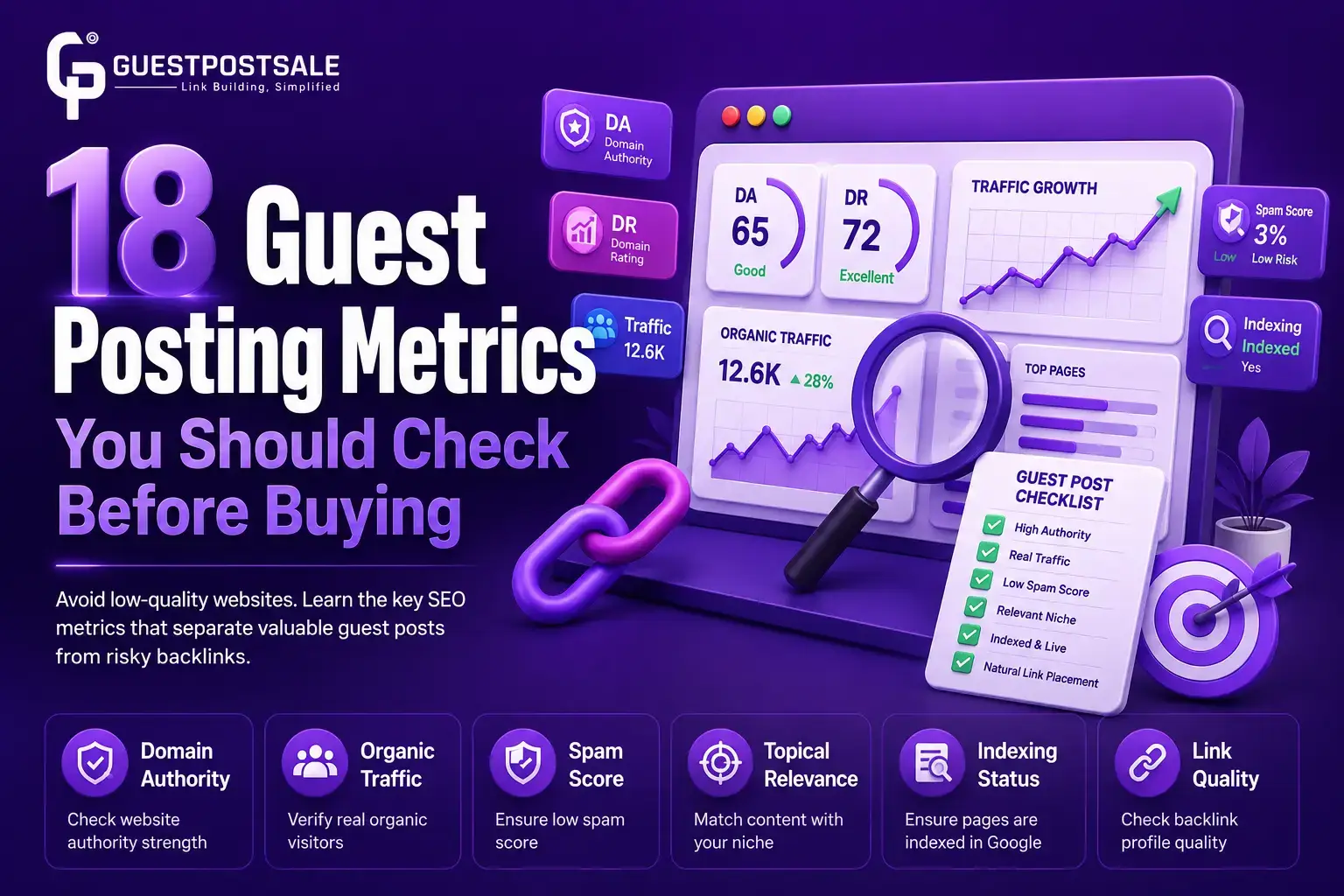
Numbers such as domain authority or domain rating can help you compare websites, but they do not tell the whole story. A publication’s relevance, editorial standards and real audience are just as important. Check whether it regularly covers subjects related to your business and whether its articles appear to serve readers rather than exist mainly to host links.
Look at recent posts, the quality of their writing and the conversations they generate. If the site has an identifiable audience, ask whether those readers are likely to care about your expertise. Also check that the proposed article will make sense in its editorial setting. A natural, useful contribution is more credible than a generic piece that feels disconnected from the publication.
For a more complete planning framework, this marketing guest posting guide covers choosing suitable publishers, developing content angles, setting budgets and reviewing results. Those decisions are worth making before a campaign scales, not after the budget has been spent.
Judge the content opportunity as well as the site
A relevant website still needs a strong article idea. Ask what the publication’s readers might learn from your contribution that they cannot easily find in another basic overview. Useful angles often come from practical questions, common mistakes, comparisons, or lessons drawn from real work.
Agree on the topic, format, audience and link placement before work begins. The article should answer a genuine reader need, with any mention of your business fitting naturally into the discussion. If the only reason for the piece is to insert a link, reconsider the placement. Thin or awkward content can undermine trust even if the publisher’s headline metrics look impressive.
Set a budget and define what success means
Guest posting costs can include publisher fees, writing, editing and the time spent managing the campaign. Work out the full cost of a placement and compare it with the value you hope to gain. A lower price is not automatically better if the site is a poor fit or the article needs extensive rework.
Before publishing, choose a small set of measures that reflect your objective. Depending on the campaign, these could include referral visits, engagement with the article, enquiries, branded searches or the quality of the audience reached. Record a baseline and review results after a suitable period. Do not rely on a single short-term metric: some benefits, such as familiarity and brand recognition, are harder to attribute directly.
Use results to decide what to repeat
After a placement goes live, note what happened and what you would change next time. Did the publisher share the article? Did visitors spend time on the page or continue to your site? Was the audience relevant? Did the content support a wider campaign? Even a placement with limited measurable traffic may offer useful learning about a topic or publication, but repeated weak results should prompt a rethink.
When the work involves several contributors, make the process manageable. Freelancers can help with research, writing, editing or campaign support, particularly when your team lacks time. For broader advice on finding clients and developing a repeatable outreach routine, Osdire’s guide to freelance cold outreach is relevant to independent professionals building their own pipeline. Osdire is a freelance marketplace where businesses can hire across categories including writing, marketing and design, which can be useful when a campaign needs specialist support.
A simple decision checklist
Before approving another placement, consider these questions:
- Does the publisher reach an audience that matters to your business?
- Can you offer a genuinely useful and distinctive article idea?
- Are the total costs clear and proportionate to the likely value?
- Do you know how you will track the placement’s performance?
- Have previous placements shown enough promise to justify repeating the approach?
If the answers are uncertain, pause and investigate rather than committing automatically. You might test a different audience, improve the content angle or redirect the budget towards another channel. If the answers are strong, another guest post can be a considered next step—not simply another item on a publishing schedule.
Conclusion
Deciding whether to buy another guest post comes down to fit, usefulness and evidence. Choose publishers for their readers and editorial relevance, create material that earns attention, and track results against clear goals. A thoughtful campaign will not guarantee a particular outcome, but it gives you a sound basis for learning what deserves more investment—and what should change before you spend again.

Why Your Headphones Pick Up the Whole Office on Calls

Transform Your Skin with RF Microneedling: Discover the Benefits at Elite Body Contouring

Revolutionizing Precision: The Advantages of Fiber Optic Laser Cutting with Macro Weld

Stunning Spring Carnival Dresses to Elevate Your Style This Season

Top Cricket Equipment Essentials Every School Should Have

Innovative Architects in Sydney: Designing Your Dream Space with Shore Architects

How to Ensure Your Home is Valued Correctly for a Quick Sale

Christopher Dare: The Untold Story of Engineer and Former Husband of Angela Rippon

The 15 Highest-Paid Rugby Players in the World

What Is Fanquer? The Digital Creator Platform Transforming Direct-to-Fan Engagement

Dr Jared Ross: Missouri Appeals Court Upholds Protection Order Over Graphic Torture and Murder Threats

Nancy Hallam: The Inspiring Life, Career, and Success Story Behind Ian Wright’s Wife
How to Ensure Your Home is Valued Correctly for a Quick Sale
Christopher Dare: The Untold Story of Engineer and Former Husband of Angela Rippon
The 15 Highest-Paid Rugby Players in the World
What Is Fanquer? The Digital Creator Platform Transforming Direct-to-Fan Engagement
Dr Jared Ross: Missouri Appeals Court Upholds Protection Order Over Graphic Torture and Murder Threats
Nancy Hallam: The Inspiring Life, Career, and Success Story Behind Ian Wright’s Wife
-
 Real Estate9 months ago
How to Ensure Your Home is Valued Correctly for a Quick Sale
-
Celebrity11 months ago
Christopher Dare: The Untold Story of Engineer and Former Husband of Angela Rippon
-
 Sports5 months ago
The 15 Highest-Paid Rugby Players in the World
-
 Technology5 months ago
What Is Fanquer? The Digital Creator Platform Transforming Direct-to-Fan Engagement
-
 Celebrity5 months ago
Dr Jared Ross: Missouri Appeals Court Upholds Protection Order Over Graphic Torture and Murder Threats
-
Celebrity12 months ago
Nancy Hallam: The Inspiring Life, Career, and Success Story Behind Ian Wright’s Wife
-

 Celebrity8 months ago
Who Is Azriel Crews? Inside the Life and Career of Terry Crews’ Daughter
-
 Celebrity11 months ago
Who Is Maisie Mae Roffey? The Private Life, Family Story, and Quiet Success of Julie Walters’ Daughter